Scanning light photography, also known as photomacrography, (SLP) provides a solution to several of the most limiting problems associated with more conventional close-up techniques. As implied by its alternate name, deep-field photomacrography, subjects recorded using this method will be rendered in focus from the details nearest to the lens to those at the farthest limit. Using conventional techniques, only a part of the subject can be in acceptable focus when recorded at magnifications high enough to resolve fine detail. Using SLP, subjects can be photographed with the kind of depth of field commonly associated with scanning electron microscopy (SEM). This can be done without the strictures imposed by SEM, where specimens must be conductive, subjected to high vacuum, and small enough to fit into the microscope's chamber. In addition, true color can be used whereas only computer assigned pseudo color is attainable with SEM and then only in the most sophisticated instruments that are orders of magnitude higher in cost than those for SLP. [see illustration below]
The principles known since the early 1960's (McLachlan, 1964), SLP has been documented for use in macro-photography demonstrating excellent results with subjects requiring up to 30X print magnification. In our case, we have worked with subjects of varying size but have concentrated on the magnification range that is in the crossover between non-macro and macro-photography, from about one fifth life size on the film to about 2.6X. SLP seems to work very nicely in this range. Since SLP uses traditional optics it is governed by physical laws for depth of field. The closer the lens to the subject and the higher the magnification required, the smaller the depth of field becomes. Since only one plane is in true focus (when ray patterns from a specific part of the subject come to cross over at the film plane), the size of the circle of confusion, variously quoted at 1/500th to 1/1000th of an inch for 35 mm formats, determines how much of the specimen appears to be in acceptable focus. The smaller the aperture, the farther away from the plane of true focus one can go before reaching the circle of confusion limits. When working at image to specimen ratios of about 1:10 or greater, the following formula for depth of field applies (Engel, 1968):
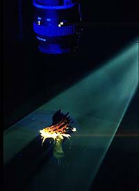
SLP overcomes the problems of depth of field by
recording only information between the maximum circle of confusion limits
on either side of the plane of true focus. To accomplish this, the subject
is mounted on a stage which moves perpendicular to the film plane. A thin
slice of light parallel to the film plane illuminates the subject as it
passes through the light source. The direction of movement can be either
towards or away from the lens as long as the travel is perpendicular to
the film plane. As the subject passes (scans) through the narrow plane of
light the image is painted onto the photographic emulsion
Equipment required to make SLP images is no longer commercially available. For those still wanting to try SLP, a working system can be built for approximately 50-100 dollars depending on how much equipment can be borrowed, rented or scavenged. The setup used to make the accompanying images consists of three standard Kodak EktagraphicTM AF-2 projectors using ELH lamps and fitted with 102-152mm zoom lenses. The projectors were positioned at a distance sufficient to project as thin a focused plane of light on the sample as possible, about 24 inches from lens to subject. To create the thin plane of light, plastic slide mounts were used to hold pieces of double edged razor blades, edge to edge, across the center of the slide mount aperture. The area above and below the metal of the blade was masked with at least two layers of metallized tape to limit the spill of light (Root, 1986). To adjust the height and level of the projectors we initially used books and cardboard shims. This is not a practical approach if you plan on doing SLP on a routine basis, but a good way to run film exposure tests to see if the rest of your setup works. Later, the purchase of equipment jacks from VWR scientific supply house provided quick and easy adjustments for height, pitch and roll [figure 2].
The camera used was a Nikon FE-2 equipped with either a Micro-Nikor 55 mm f 3.5 lens with or without a PK-13 extension ring or a Nikor 24 mm f 2.8 lens reversed using a Nikon BR-2 ring. The shutter was set at B and a locking cable release was employed. The camera was mounted on a table top copystand. The lens was fitted with a CokinTM filter adapter and Cokin blue filters were used to color balance the light. If added control of color balance is needed, color compensating (CC) filters provide color corrections in densities ranging from .025 to .50 (the decimal is normally omitted in the designation). The stage was a modified dissection microscope stage which was moved either up or down using a focusing motor attachment controlled by a foot switch . The revolution rate is fixed at about 2 rpm which gives a linear stage speed of about 38mm/min. in our case. Another good source for a stage is described by Nile Root (Root, 1985) who used a telescope eyepiece focusing assembly connected to a 12 volt DC motor. Any smooth rack and pinion movement which can be motorized will work. We found the microscope stage had the advantage of greater vertical travel, 6 inches rather than 3 inches, which is needed for larger subjects. Film selection was based on several factors; since the main purpose of photographing these images was to document a large shell collection, 35mm slides were considered the best choice for cost and cataloging purposes. To ensure maximum detail, color saturation and for archival qualities Kodachrome 25 ISO 25/15o was selected. To test our home made SLP system and to determine approximate exposure we first used a roll of Technical Pan 2415 film rated at ISO 25/15o. A series of exposures were made in 1/2 stop increments using the aperture control ranging from f 5.6 to f 22. After this series was developed (using Technidol LC developer) and evaluated, the best range of apertures was determined. Taking into consideration the addition of filters for color balance f 8 to f 11 gave the best results. The last consideration was the color balance of the Kodachrome. Ektagraphic slide projectors provide a strong source of illumination rated at approximately 3350K, a bit warm for natural results with daylight balanced film. By running several series of bracketed exposures with different combinations of Cokin filters (023, 024, 025) the best combination was selected for correct color balance. This procedure is necessary every time a new film lot is purchased, because all color films have slightly different color balance. It is, therefore, advisable to purchase a "brick" of film (twenty rolls of film packaged from the same emulsion lot) if color rendition is critical. The benefits of SLP do not come without some sacrifice. The highly directional lighting used is both a blessing and a curse. The images, because of the lighting, give a heightened sense of detail. For the shells it is often the case that minute details become much more apparent in the photograph than when viewed with less directional lighting. Since this is also the case with tiny pieces of dust and lint, preparation of SLP samples requires careful inspection and cleaning using compressed air or a soft brush. A fine tipped pair of forceps (#5 DumontTM) and a good loupe or dissection microscope are also very handy for this purpose. Contrast control is another potential problem with SLP. Again, due to the type of lighting used, photographs can be extremely harsh. This is most common with deeply textured subjects. The use of three light sources rather than two will help reduce contrast for some subjects, while adjustment of sample alignment to the plane of light will sometimes reduce exaggerated shadows and harsh edge effects. Finally, selection of negative rather than positive film helps to keep the shadows from blocking up and subsequent loss of detail is reduced. In previous articles on SLP, light piping has been described as a problem when photographing translucent subjects. Such piping can cause ghost images on a photograph. We found this did not present much of a problem with the shells even though many of them are translucent. This is attributed to the selection of Kodachrome 25 film which has an extremely high threshold. Due to the high threshold, the areas that the light is piped to on translucent subjects are not nearly bright enough to create ghost images. The very nature of SLP gives a dramatic appearance to subjects photographed using this technique. Only the subject is recorded on the film leaving all else a deep rich black. This is often beneficial, but at times it can present problems. For instance, if the subject being photographed is very dark it tends to blend in with the background. Nile Root of RIT has written of experimentation using double exposure to add colors to the background (Root, 1985). At this time, however, we have not found any articles that describe in detail how this is done and what the results have been. The original intent of using SLP was to begin
documentation of the Chester A. Melville shell collection which is housed
in the Dept. of Zoology, Arizona State University. This collection is one
of the larger privately amassed shell assemblies in the world and was
placed at ASU on the condition that it be shared with the public on a
regular basis. In addition to public displays of selected groups of the
shells, it was felt that a method of showing even the rarest and most
delicate of the shells should be investigated. Conventional
macro-photography was rejected due to depth of field problems. Since the
first shells were photographed using scanning light photomacrography, we
have worked with specimens such as tiny insect leaf parasites and their
habitat, specific types of ants and butterfly wings. Bits of acorns and
other seeds and leaves all have been "pushed through the plane" in the
name of clear, unambiguous scientific documentation and aesthetic
gratification. ACKNOWLEDGEMENTS: We would like to thank Dr. Nancy Mozingo for her meticulous preparation of several of the shells and suggestions provided towards this article. REFERENCES: McLachlan, Dan, Jr. 1964. Extreme Focal Depth in Microscopy. Applied Optics, Vol. 3, No. 9, pp 1009-1013. Engel, Charles E. 1968. Photography for the Scientist. Academic Press, London and New York, pp 120-123. Root, Nile. 1985. Light scanning photomacrography - a brief history and its current status. Journal of Biological Photography, Vol. 53, No. 2, pp 69-77. Root, Nile. 1986. Deep-Field Photomacrography. Photomethods, Vol. 29, No. 5, pp 16-18 Root, Nile. 1991. "A simplified unit for making deep-field (scanning) Micrographs." Biological Photography, Vol. 59, No. 1, pp 3-8 FIGURE CREDITS: Figures 1 AND 2 by Charles Kazilek and based on earlier illustrations. CC BY SA 4.0 |
|||||||||||||||||||||||||||||||||||||||||||||||